MJF 3D Printing
3D printing was founded in 1981 when Hideo Kodama produced the first published existence of prototyping method with the use of photopolymers and stereolithography. This sparked a revolution of various methods of rapid prototyping methods that were categorized as 3D printing. Within 15 years, there were technologies created using DMLS, FDM, SLA, and SLS. Learn more about those methods here. Throughout the following years, the technologies were refined while even more were introduced. In 2014, HP introduced Multi-Jet Fusion printing.
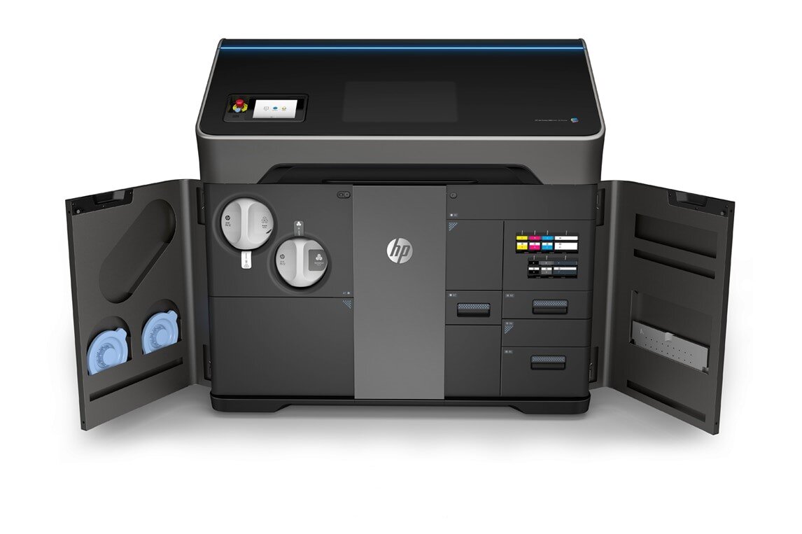
Figure 1: HP MJF Printer
Both SLS and MJF are powder bed fusion technologies. The primary difference is the curing method. MJF printing creates parts by dispersing a curing and detailing agent across a thin layer of powder and then thermal energy in the form of infrared light is applied to fuse the particles.
This creates high density, low porosity parts with functional mechanical properties and high accuracy. It does not require support structures which allows for a more refined surface finish as well. See the following table for printings specifications.

Table 1: Printer Specifications
Not only is this method highly accurate, with potential of incredibly fine features, it is also very time efficient. As the printing process is very fast compared to alternative methods, this allows for smaller layer thickness for the same lead times. All while remaining competitive in terms of cost. Using the bracket shown below, which has a bounding box with dimensions of 150 x 120 x 90 mm, a cost analysis was done with various quantities.

Figure 2: Bracket Used for Pricing Analysis
The results are shown by the following table.

Table 2: MJF Pricing Analysis
As can be seen by the results, even for low quantities, MJF outmatches SLA and even outmatches FDM and SLS as the quantity increases. MJF will also produce higher quality parts than FDM which should be kept in mind when considering FDM to be cheaper at lower qualities.
An additional note is that since MJF is so new in the 3D printing world, there is a lot of room for improving what is already a strong competitor. In 2018 they released the HP Multi-Jet Fusion 380 and 580 printers which allow each individual voxel to be printed with its own color. A voxel is a three-dimensional pixel, which essentially is a small cube with side dimensions of 50 microns each, and together they form a part. This means fully functional colored prints can now be created. With the advent of this voxel customization technology, they soon hope to apply this concept to materials. This would allow parts with various mechanical properties to be printed all at once. From surface finish, translucency, and elasticity to conductivity, the possibilities are endless with what MJF printing could create.

Figure 3: Fully Colored Print
The current options for materials provided by HP are variations of PA 11 and PA 12 nylons with various properties to ensure the part fits your needs. HP has also begun to partner with others to widen your selection of materials. They now have a thermoplastic polyurethane material available from BASF which allows you to create flexible and functional parts. As this is a new technology, more materials will be available as time progresses.
When designing for MJF printers, it is advised that you try to keep your wall thickness to at least 1 mm, even though the minimum is 0.5 mm. The ideal wall thickness is approximately 2-3 mm. Try to hollow out your part as much as possible, especially when areas thicker than 20 mm exist. If you have a hollow area in your part, be sure to include at least two holes with a minimum diameter of 2 mm to help with the post-processing of powder removal. Lattice structure can be added internally to regain structural rigidity but be sure to keep at least 1 mm clearance between lattice beams. If you are printing an assembly, a clearance of at least 0.5 mm should be provided for interlocking parts. If you plan to emboss or engrave details the minimum suggestions are as follows, line thickness: 0.5 mm, depth: 1 mm, overall height: 2.5 mm. Engraving or embossing textures can have a minimum thickness of 0.25 mm. Last but not least, large flat surfaces should be avoided as much as possible as they are prone to warping.
Thanks for reading our Blog, for any questions or contract services please feel free to contact us!