SolidWorks: Fully Define Sketches
Sketches tend to move just enough to be irritating if not fully defined: features or even assemblies may change without the designer’s knowledge at times. The initial stages of a model derive off the sketch, so properly defining a sketch is important in the professional world of engineering.
DIMENSIONS
The team here at Perception Engineering creates hundreds of sketches each day. All the sketches need to be fully defined to ensure future changes to the sketches will not throw off the rest of the sketch. Not only will defining sketches make future changes easier, but the scale of the sketch is able to be easily determined.
Sketches are the simplest way to get ideas on paper, whether those ideas are drawn by hand or on a computer, the first stages of creating 3D models come from sketches. The initial sketches provide a rough idea of size and proportions, designing with the proper shape is just as important as defining size and constraints in sketches.
* Dimension Properties
* Dimension Techniques
* Dimension Changes
SKETCH-DIMENSIONS
Dimensions within a sketch, when done properly, should allow any user to recreate the sketch or model based entirely on looking at the drawing associated with the model. Properly defining all geometry that makes up the sketch will eliminate any confusion to the reader. Not only will dimensioning a sketch provide insight into the model but will prevent any unexpected changes. Not defining the geometry within a sketch could result in the initial sketch changing without warning. Dimensions give insight into size, shape, and constraints.
Figure 1: Size, Shape, and Constraints
When comparing the left and right-side sketches in Figure 1, the right-side sketch is the obvious choice. Why? The right-side defines the overall size, shape, and constraints of the sketch. From the defined sketch, it is known that the sketch will be 3.00” long and 1.00” wide. In this blog, the proper techniques to properly define a sketch will be explained and you will be well on your way to becoming an expert CAD Designer.
SMART DIMENSION
SolidWorks provides many solutions to achieve defined sketch-dimensions. In this tutorial, all dimensions will be done with Smart Dimension located in the Command Manager Hot bar.
Figure 2: Command Manager
BASIC APPROACH
Dimensioning sketches in SolidWorks is made simple with auto-scaling. The developers of SolidWorks programed auto-scaling based on the initial dimension added to the sketch. First defining the overall shape and size of the sketch is the most efficient method when getting into larger models. Then working down until all the tiny tedious geometry of the sketch are fully defined are the next steps to properly defining a sketch. Using the left-side sketch shown in Figure 1 as the starting point, notice how all the lines are blue? These blue lines tell us that the sketch is underdefined and can be moved around with the click of a mouse.
Figure 3: Initial Sketch
Once the initial sketch is made as explained in Perception Engineering’s Sketches Blog, the first step is to define the overall size. After selecting Smart Dimension as shown in Figure 2, the arrow cursor will now have the Smart Dimension Icon under it. To define the overall; first, the width dimension needs to be set. Click on the large circle located on the origin of the sketch, the Dimension Modify popup will prompt the user to set the radius of the circle.
Figure 4: Dimension Modify Popup
Now that the width is set, the length of the sketch needs to be defined before moving onto the smaller pieces of geometry that makes up the part.
Figure 5: Setting the Length
One trick of Smart-Dimensioning in SolidWorks is the “Shift” key on the Keyboard. Holding the “Shift” key and selecting the outer most part of the circle and again while holding “Shift” selecting the other outer most edge of the sketch will grab the overall length of the sketch as shown in Figure 5.
DIMENSION SPACING
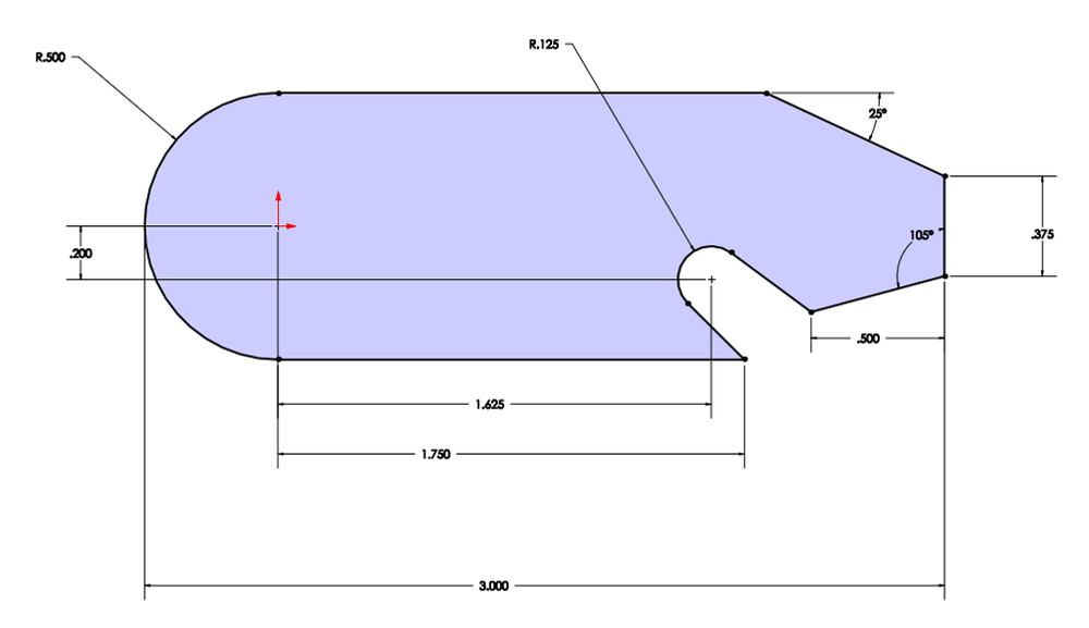
Once the overall dimensions are in place, the sketch will auto scale accordingly to fit the same proportions of the previous geometry dimensioned. The nice thing about Smart-Dimensioning in SolidWorks is the feature identifier: dimensioning horizontally, vertically, angles or radii can all be done with the Smart-Dimension tool. As seen on the right-side sketch in Figure 1 and in the figure below, the sketches geometry is defined with radius dimensions and angle dimensions.
Figure 6: Dimension Spacing
Placing random dimensions all over the screen is not a good practice and can be rather confusing for anyone trying to work on the CAD model. Good practice is proper spacing and orientation of all dimensions within the sketch. Notice in Figure 6 how all the dimensions are nicely spaced and visible, this allows the designer to review the sketch without confusion. Due to the unlimited number of ways to properly define this sketch, it is essential to keep the sketch dimensions clean, clear, and to the point. Instead of using angle dimensions in Figure 6, the length and height of the line could be defined instead. Again, there are unlimited ways to define a sketch so having clean and clear dimensions of the sketch is important.
FULLY DEFINED SKETCH
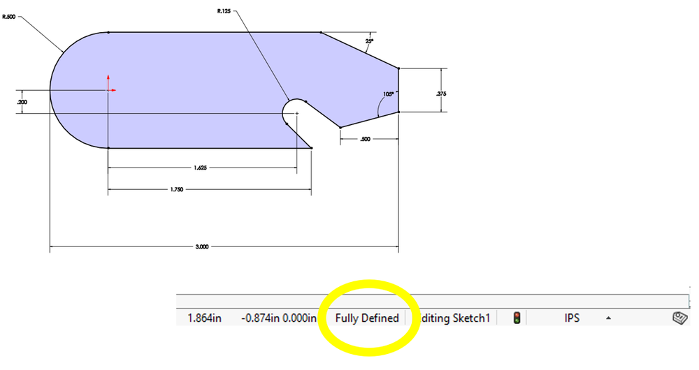
The sketch is fully defined if the lines on the sketch are all black. This means that there can be no unexpected changes within the model due to all the geometry of the sketch being fully defined. On more complex sketches with 100+ lines, looking on the bottom right corner the SolidWorks interface will help tell the user if the sketch is fully defined.
Figure 7: Fully Defined
Having a sketch be fully defined is not only important for displaying all the key geometry of the sketch, but it allows for easier changes. Double-clicking on any dimension will prompt SolidWorks to bring back the Dimension Modify popup. Changing the overall length from 3.00” to 4.50” is as a few clicks away; however, if the model is not fully defined the sketch will change without warning and the geometry may unpredictably change.
Figure 8: Changing Dimensions
The team here at Perception Engineering is constantly refining our skills to be the most efficient engineering solution. The basic skill of properly defining a sketch carries over into ease of modeling massive multi-million-dollar machines. Most projects will require some changes and tweaks to the model, and if the sketches are not fully defined there might be some frustration due to the models moving out of control with each change.
That’s all for now! You now know how to properly define a sketch and make changes to existing geometry. We're so glad you took the time to read our blog! If you have any questions or need our contract services, please feel free to reach out to us anytime. We're always happy to help!


