Solidworks Sheet Metal Gauge Tables
If you’ve worked with sheet metal then you know the importance of sheet metal properties such as bend deduction, bend allowance, gauge thickness, K-factors, bend radius, etc. If you design a part with incorrect properties, it will not be manufactured as intended. This is especially notable when working with sheet metal assemblies and the error will stack up, creating parts that do not fit together correctly at final assembly. Sheet metal gauge is based on the weight of the sheet, therefore a sheet of two different materials with the same thickness may have different gauge numbers. When working with sheet metal, a gauge table in SolidWorks can be used to ensure the correct thickness is chosen for your selected material, along with the manufacturing properties as well (k-factor, bend radius, etc.). Proper use will help your part to be manufactured just as it was designed within a standard tolerance.
NOTE: While there is a standard (Manufacturers’ Standard Gauge), gauge can vary slightly between manufacturers. For the best results, contact your manufacturer for gauge table information and manufacturing properties before carrying out your design.
Before continuing you will need a filled-out gauge table in Excel that will work with SolidWorks. Solidworks’ templates for two variations of this template can be downloaded below with added instructional content. The first is assuming a consistent k-factor across all gauges and bend radii. The second is for varying k-factors among different gauges and bend radii.
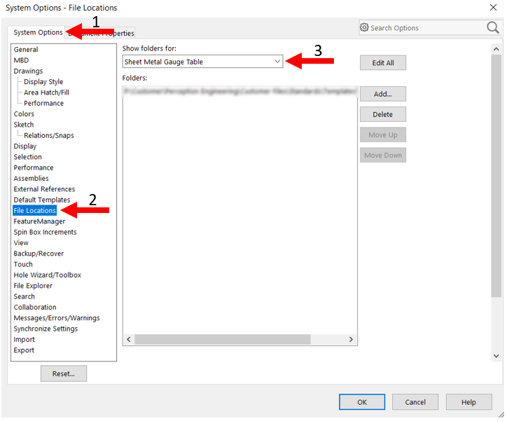
Save these in your desired location and update your file locations. To do this, go to Tools → Options, or select the gear icon the right of the save icon at the top of your window. In the Systems Options tab, go to the File Locations Page, and select Sheet Metal Gauge Table from the dropdown. Delete the existing path and add the path to where you saved your gauge table.
When designing a sheet metal part in SolidWorks, there are a couple methods you can use to help ease the process of entering this information and cut down on potential errors.
Method 1: Manual Gauge Table Selection
To begin, create a sketch and then select the Base Flange/Tab command from the sheet metal tools. You should be presented with the following display.

Without a gauge table, you would have to enter the parameters such as the thickness and bend allowance manually. This is time consuming, especially if you have to search for this information prior to entering it, as well as presents more potential for error. By selecting the Use gauge table option under the Sheet Metal Gauges section you will be presented with the following display.
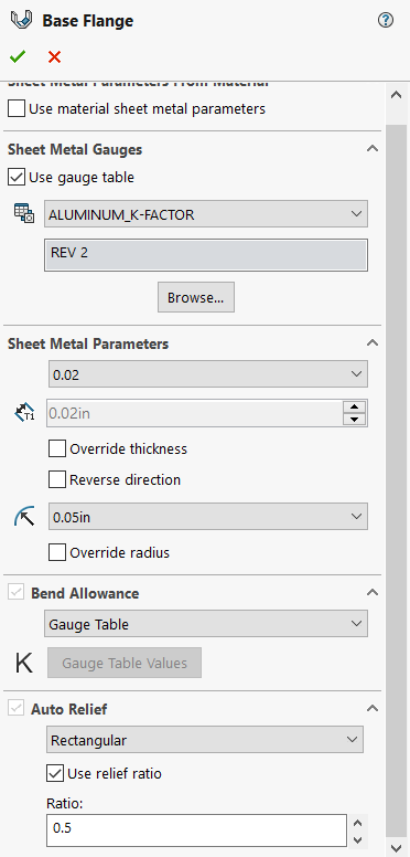
You will now have drop downs for all the information entered on your gauge table. Select which gauge table you would like to use in the first drop down and you will be presented with the ability to choose thicknesses, bend radius, and by selecting K-Factor from the Bend Allowance drop-down, this will automatically be applied as well. If you need to enter a custom value, click on the Override thickness or Override radius selection boxes.
NOTE: If your gauge tables are not appearing in the dropdown menu, try saving them as an .xls filetype rather than an .xlsx.
Method 2: Linking Gauge Table to Custom Material (Only on 2019 and Later)
If you have access to SolidWorks 2019 or later, you are able to link a custom material to your gauge table to ensure the same gauge table is used across all parts of the same material. To do this, right-click on the Material in your feature tree and select Edit Material.

Right-click on the Custom Materials folder and select New Library, name it Sheet Metal. You can add a new custom material by right-clicking on this new folder and selecting New Material or by copying and pasting an existing material and modifying it as you desire. Once you have the material in the library, go to the Sheet Metal tab at the top of the window.

Ensure Gauge Table is selected and select the appropriate gauge table for your material from the drop-down menu. Select Apply to apply the material to your part. Then, create a sketch and then select the Base Flange/Tab command from the sheet metal tools. Just as with the first method, you should be presented with the following display.

However, this time select Use material sheet metal parameters under the Sheet Metal Parameters From Material section. You will then be presented with a similar display as method one, except it will automatically select the gauge table based off that selected in your material’s sheet metal properties and you will not have the ability to change this.

Just as with the first method, you can now go and select the appropriate values from the provided drop-down menus as well as override these values if desired.
Thanks for reading, for any inquiries or contracting services, please don't hesitate to reach out to us!