SolidWorks: Convert And Offset Entities
Convert/Offset Entities
Creating sketches on an existing surface is as simple as a one-two click within the SolidWorks interface, but the team here at Perception Engineering sometimes needs to create sketches based off surfaces and in other cases sketches based off sketches. To do this the sketch commands Convert Entities and Offset Entities are used on a consistent basis. Continue reading to learn the commands Convert/Offset Entities within SolidWorks.
*Introduction to Convert Entities
*Introduction to Offset Entities
Convert Entities
The initial steps to create a sketch based on a surface features are the exact same as creating a basic sketch. Read the How to create Sketches blog to learn how to create the initial sketches. The Convert Entities sketch feature creates a sketch derived from a surface.
Figure 1: Surface Sketch
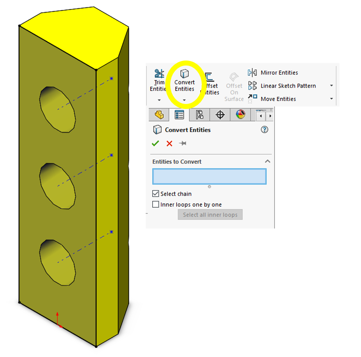
After selecting the surface click on the Sketch Icon to start a sketch on the surface plane. Next select Convert Entities Icon on the Command Manager to create geometry on the outside edges of the selected surface. This will display in black lines as a result of the sketch becoming fully defined.
Figure 2: Convert Entities Tool
To copy the three inner circles, we will follow the same steps. Within the sketch, again select the Convert Entities Icon and select the geometry that you wish to copy. The selected edges will display in the feature manager on the left-hand side of the screen. Once all the desired edges are selected click the green check mark. That’s it! The Convert Entities feature is simple but an effective tool when working with tedious models that have a lot of detail.
Figure 3: Convert Entities Edges
The Offset Entities will be the next focus. This sketch tool is used a lot here at Perception Engineering as it allows for fewer dimensions to be used and fewer clicks of the mouse. We believe fewer clicks of the mouse or buttons will save a large amount of time; however, always ensure the final product is quality over efficiency. Just because fewer mouse clicks are used, this does not mean that in the long run, time will be saved. You always need to keep the final design intent in mind, only using Convert/Offset Entities in areas where it will not cause more work down the line.
Located next to the Convert Entities tab, the Offset Entities does exactly as it sounds, it takes an existing sketch and offsets it to the specified dimension. Once the Parameters are set and all the selected edges are identified, the offset entities will be outlined in yellow and if everything looks correct, click the green checkmark.
Figure 4: Offset Entities
The red arrow in Figure 4 is the Reverse Direction checkbox, this will switch the direction of the offset. The other checkboxes at the bottom shown with the larger arrow will turn the offsets into construction lines.
The feature now has all the desired lines intended for the next step. The original Offset Entities circles have been modified to have the bottoms cut off; notice the .125” dimension on the top circle, the Offset Entities tool added that dimension which is fully defined. In addition, the outside edges have been turned to construction lines. The other dimensions, .127” and .555”, have been added to fully define the bottom of the circle.
Figure 5: Final Modifications
To finish off the model, the created sketches have been Extruded to represent something similar to a Stop Light.
Figure 6: Stop Light
That’s all for now! You now know how to use the sketch tool Convert Entities and Offset Entities.
We're so glad you took the time to read our blog! If you have any questions or need our contract services, please feel free to reach out to us anytime. We're always happy to help!


