SolidWorks: Cut-Extrude Basics
In this blog, we will be focusing on the Extruded Cut feature within SolidWorks. This is a handy feature to aid in material removal of a 3D model using 2D sketches. We will be taking a deeper dive into the terminology, as well as how to access the feature from different menus.
Extruded Cut
Using the Extruded Boss/Base model created in the Extruded Boss/Base blog, we will modify the 3D block to include a circle feature by removing material. The Extruded Cut feature can be found on the features tab in the Command Manager interface as shown in Figure 1.
Figure 1: Extruded Cut Feature
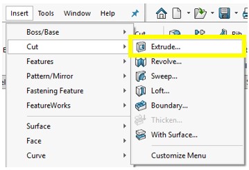
You can also go to the toolbar and click Insert -> Cut -> Extrude to pull up the Cut-Extrude Feature menu as well.
Figure 2: Insert Cut Extrude
Once the Extrude menu appears on the left-hand side of your screen, it will prompt you to select a plane or sketch that will be used to create the 3D model feature.
Figure 3: Selecting a Sketch/Plane
Select the desired 2D sketch from the feature tree by clicking on the sketch name as shown.
Figure 4: Selecting a Sketch
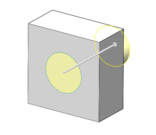
The Cut-Extrude feature will then preview the shape of cut based on the selected sketch.
Figure 5: Extruded Cut Preview
The Cut-Extrude feature button will prompt you to set parameters in the menu shown in Figure 6.
Figure 6: Cut-Extrude Feature Menu
From
Under the “From” header there is a drop-down list containing a variety of options of where to start the Cut-Extrude from.
Figure 7: From Dropdown Menu
The “From” options are as follows:
Sketch Plane: The plane in which the sketch was created
Surface/Face/Plane: A different surface/face/plane than which the sketch was created
Vertex: A point
Offset: An offset distance from the original sketch plane.
The most common is Sketch Plane, and that is what will be used for this tutorial.
Direction 1
Under the “Direction 1” header there is a drop-down list containing options for the distance you wish to cut.
Figure 8: Direction 1 Dropdown Menu
The “Direction 1” options are as follows:
Blind: A specified distance
Through All: Through the entire part in one direction, normal to the sketch plane
Through All - Both: Through the entire part in two directions, normal to the sketch plane
Up To Next: Up to the next surface of the part
Up to Vertex: Up to a point/vertex
Up To Surface: Up to a surface/plane/face
Offset From Surface: A specified distance away from a surface/plane/face
Up to Body: Up to a body within the model
Mid Plane: A specified total distance in both directions, normal to the sketch plane
“Blind” and “Through All” are basic and the most common directions selected when using the Cut- Extrude feature. You can also toggle the direction of the cut to reverse direction by clicking the double arrowed icon as shown in Figure 9.
Figure 9: Reverse Direction Icon
Depth
Within the depth box is where the desired length or “depth” of the Cut-Extrude will be entered.
Figure 10: Depth Thickness Parameters
Direction 2
There is another heading called “Direction 2” that has the same capabilities as Direction 1, but this will be in the opposite direction, normal to the sketch plane. To choose Direction 2 feature, select the check box next to the heading “Direction 2”.
Figure 11: Direction 2 Icon
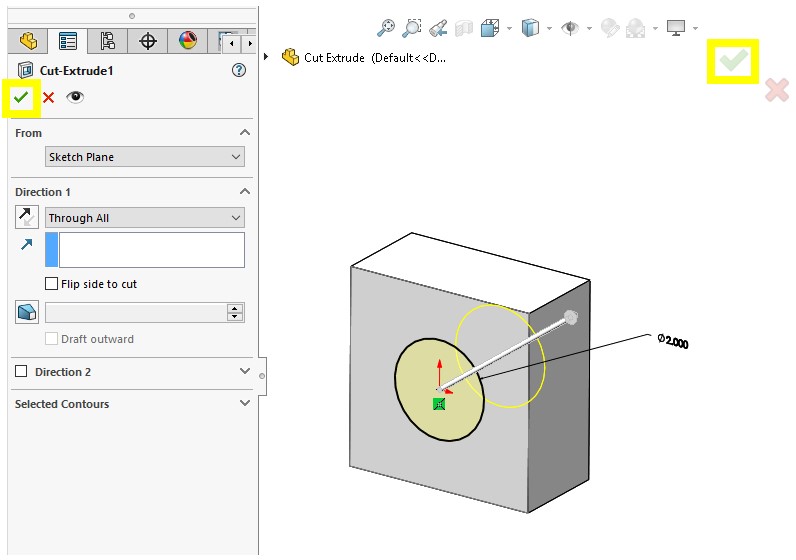
Once the Cut-Extrude parameters are finalized, click the green check mark in either the upper left or right-hand corners, to create the feature.
Figure 12: Cut-Extrude Finalization
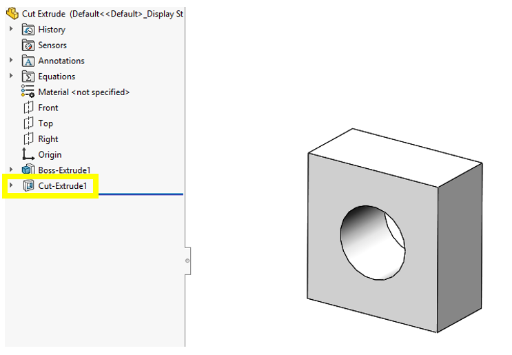
Once you select the green check mark, the extrude cut feature should appear within the feature tree, and the material should be removed from the part.
Figure 13: Cut-Extrude
The Cut-Extrude feature is a very useful tool. In the manufacturing world, it can be a common practice to start with stock material (i.e. a standard plate size) and proceed to use the Cut-Extrude tool to remove material as you would during the machining phase.
That’s all for now! You now know the basics to create a Cut-Extrude. This is the start of editing Solid 3D models with the geometry defined in sketches. Thanks for reading, for any inquiries or contracting services, please don't hesitate to reach out to us!


